If you have just joined us at this blog site, you will want to be sure to start reading with the first post. The order of posts in the blog is the most recent is at the top — scroll down to see previous posts. This series of daily posts is about how to get started in radio controlled model airplanes. You won’t want to miss any of the preliminary information.
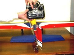
The following photos will help explain how the R/C model airplane is controlled remotely with the radio equipment. The first picture shows the model and the 6 channel radio transmitter that is used to fly this model. This is not a trainer and really not the best suited to learn how to fly with. Notice that this is a low wing pattern plane. It is best suited to high speed and intricate aerobatics. The controls work the same for a high wing trainer, but we didn’t have one available at the time for demonstrating how the plane is controlled. This R/C airplane has a .46 OS engine installed and it has been flown many times without accident.

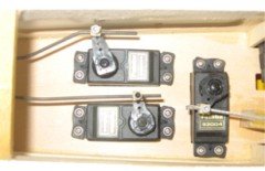
The next picture shows the inside of the model plane’s fuselage with three servos installed. On the right, crosswise to the length of the fuselage is the throttle servo. Note the control arm and the connection to the push rod. Typically, most servos move a total range of 90 degrees, however, with the computerized radio system, you can limit the range of the servo’s movement to match the full range needed for the engine’s throttle mechanism. By doing this you will prevent overloading of the servo motor. The other servos in this model are used to control the elevator, rudder and ailerons. The elevator controls how the R/C model airplane climbs or descends when in flight. The rudder is used to control the model when maneuvering on the ground and in conjunction with the ailerons to steer the aircraft in flight.
Below, are two photos showing the rudder in both the left and right position. Moving the rudder towards the right causes the model to turn to the right and moving the rudder to the left turns it to the left. Note, the rudder is controlled with the left joystick or gimbal. It is set up so that to steer to the left, you move the lever to the left and vice versa to steer to the right.

Next are two pictures of the engine showing the carburetor and needle valve. The throttle control is also on the left joystick and full forward is full speed and all the way back is idle speed. The gimbal for the throttle is set up without springs to return it to center position. The other gimbals or joysticks return to center when the pilot releases the levers. You have to look close, but the left photo shows the joystick all the way back and the throttle almost closed (idle speed). On the right the joystick is all the way forward and the throttle is wide open (max speed)


Now, we’ll move on to the elevator movement. Notice that the right joystick is moved all the way back for up (ascent) and all the way forward for down (descent), The elevators are the hinged portions of the horizontal stabilizer and the rudder is the hinged portion of the vertical stabilizer.


The next two pictures show how the ailerons are moved to bank the R/C model airplane to the left and to the right. On the transmitter, the right hand joystick moved in a right and left direction, control steering by banking the model. When you want to bank to the right, you move the joystick to the right and the right aileron moves upward. Move the joystick to the left to bank the plane to the left and the left aileron moves upward. It is difficult to see in the picture, but the ailerons move in opposite directions of each other. To bank to the right, the right wing tip must move down and the left wing tip must move up. We must always do a pre flight check of all control surfaces and the way I remember which way the ailerons move is for the wing to tip down in the direction that we move the joystick.


That covers the basics of how the R/C radio controls the model. We will go into more detail as we get to the point where we are ready to begin flying. Next time we will take a little break and give ourselves a little time for all the information to “soak” in. Hopefully, this will help provoke a few questions.
I want to thank my son, Jeremy and his friend, Kristin, for the use of his radio controlled model airplane and for helping with the pictures. That is his “ever-so-steady” hands that are demonstrating the movement of the joysticks. Just watch his hands, he is so steady his fingers never leave his hands while flying.